OMCL-TR400PB / OMCL-TR800PB / OMCL-RC800PB
Discontinued
OMCL-TR400PB-1 / 34 chips, Both side gold coating
OMCL-TR800PB-1 / 34 chips, Both side gold coating
OMCL-RC800PB-1 / 34 chips, Both side gold coating
for DC (contact) mode AFM and LFM
Catalog number
| Small quantily unit | wafer unit | |
|---|---|---|
| 34 chips/unit | Not available now | |
| Soft type | OMCL-TR400PB-1 | - |
| Standard type | OMCL-TR800PB-1 | - |
| LFM type | OMCL-RC800PB-1 | - |
OLYMPUS pyramidal tip with gold coating designed for contact mode operation.
SEM image of sharpened pyramidal tip
Tip
The picture below (left) is an SEM image of a sharpened pyramidal tip with tip-side coating of gold. As in the picture, the pyramidal tip is sharpened toward the tip apex. The tip has an uneven surface due to the gold cluster. (The right image is of the standard pyramidal tip without gold coating.)
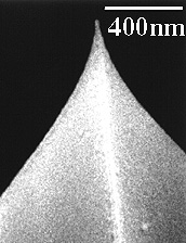
- Tip shape : sharpened square pyramidal (hollow tip)
- Tip height : 2.9 µm
- Tip radius : less than 30 nm
- Tip angle (face to face) : 25 - 45 deg. (top to around 300nm down)
- Tip material : Gold coated silicon nitride
Dimensions of levers
Cantilevers of OMCL-TR series
Two pairs of different shapes of triangular cantilevers protrude from both sides of a glass chip.
Lever thickness:
400nm and 800nm
Cantilevers of OMCL-RC series
Four different shapes of rectangular cantilevers protrude from a glass chip.
Lever thickness:
800nm
Metal coating
[Reflex coating]
Thin gold/chromium film is coated on the back side of the cantilevers for reflecting light from a deflection sensor in the AFM equipment.
[Tip side coating]
Thin gold/chromium film is also coated on the tip side of the cantilevers in the series of OMCL-TR/RC***PB- types. Because of the over coating on the tip side, the radius of the tip of the OMCL-TR/RC***PB- types become blunter, 40 nm or less, than that of OMCL-TR/RC***PSA- types, 20nm or less.
Below is the gold thickness on the levers of the tip side. According to the tip sharpness described above, the gold thickness at the tip apex must be thinner than those values.
| OMCL-TR400PB- | OMCL-TR800PB- | OMCL-RC800PB- | |
|---|---|---|---|
| Gold thickness on Tip-side (nm) | 40 | 50 | 50 |
Dimensions of chips (substrates)
Either triangular or rectangular cantilevers extend from a glass chip. Each chip is connected at the bottom of the glass chip and makes a chip array (call it "cantilever strip"). The left illustration shows a part of the array of rectangular cantilever chips.
Mechanical properties of levers and tips
Stiffness [N/m] and resonant frequency [Hz] of each cantilevers are Calculated values under the vacuum condition, or no-damping condition.
| Lever | Tip | ||||||
|---|---|---|---|---|---|---|---|
| thickness (nm) |
length (µm) |
width (µm) |
spring const. (N/m) |
resonant freq. (kHz) |
height (µm) |
radius (nm) |
|
| Triangular cantilever with reflect coating | |||||||
| OMCL-TR400PB- | 400 | 100 200 |
* | 0.09 0.02 |
32 10 |
2.9 | 30 |
| OMCL-TR800PB- | 800 | 100 200 |
* | 0.61 0.16 |
68 22 |
2.9 | 30 |
| Rectangular cantilever with reflect coating | |||||||
| OMCL-RC800PB- | 800 | 100 100 200 200 |
20 40 20 40 |
0.42 0.82 0.06 0.11 |
64 66 17 17 |
2.9 | 30 |
note:
The resonant frequency of each of the cantilever shift lower in water than in air because of the water damping. For instance in OMCL-TR400PSA-, the resonant frequencies of the 100µm and 200µm long cantilevers shift around 7kHz and 3kHz in water respectively.
Applications
- Contact mode AFM and LFM operations
Silicon nitride tips sometimes stick to sample made of silicon nitride during the scanning. Gold coating works as a solid lubricant to avoiding this. - Contact probing of IC devices
- For functionalizing tip surface with -SH base and -NH2 base
These gold coated tips are recommended because utilzing gold for this purpose is a very familier protocol among biologists and chemists. In force curve analysis to estimate a binding force between molecules, the functionalized tip is often used.
Miscellaneous
FAQs about the cantilevers this page (here).