OMCL-TR400PSA Discontinued
OMCL-TR400PSA-HW / 245 chips, Reflex side gold coating
OMCL-TR400PSA-1 / 34 chips, Reflex side gold coating
for DC (contact) mode AFM and LFM
Catalog number
| Small quantily unit | wafer unit | |
|---|---|---|
| 34 chips/unit | 245 chips/wafer | |
| Soft type | OMCL-TR400PSA-1 | OMCL-TR400PSAHW |
| 34 chips/unit | 490 chips/wafer | |
| Standard type | OMCL-TR800PSA-1 | OMCL-TR800PSA-W |
| 34 chips/unit | 490 chips/wafer | |
| LFM type | OMCL-RC800PSA-1 | OMCL-RC800PSA-W |
OLYMPUS pyramidal tip (below) is stably sharpened by our special fabrication process, and its small radius of the tip are achieved. OLYMPUS introduced this type of the tip in the first time in the world in 1991. You never doubt this type of the tip becomes standard for contact mode AFM measurements.
The tips are made of silicon nitride, which is less prone to wear than single-crystal silicon. This helps to minimize image changes caused by wear of the tip.
SEM image of sharpened pyramidal tip
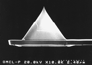
Tip
Below is an SEM image of a sharpened pyramidal tip (side view). As can be seen in the picture, the pyramidal tip is sharpened toward the tip apex.
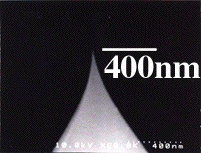
- Tip shape : sharpened square pyramidal (hollow tip)
- Tip height : 2.9 µm
- Tip radius : less than 20 nm (15 nm (typ.))
- Tip angle (face to face) : 25 - 45 deg. (top to around 300nm down)
- Tip material : silicon nitride (*)
Dimensions of levers
Cantilevers of OMCL-TR series
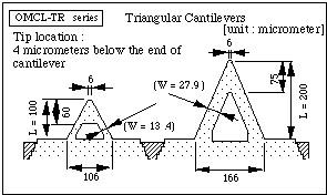
Two pairs of different shapes of triangular cantilevers protrude from both sides of a glass chip.
Lever thickness:
400nm and 800nm
Cantilevers of OMCL-RC series
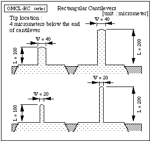
Four different shapes of rectangular cantilevers protrude from a glass chip.
Lever thickness:
800nm
Metal coating
[Reflex coating]
Thin gold/chromium film is coated on the back side of the cantilevers for reflecting light from a deflection sensor in the AFM equipment. Transparency of the lever with reflex coating for visible light is 1% or less.
Dimensions of chips (substrates)
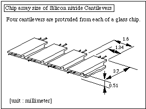
Either triangular or rectangular cantilevers extend from a glass chip. Each chip is connected at the bottom of the glass chip and makes a chip array (call it "cantilever strip"). The left illustration shows a part of the array of rectangular cantilever chips.
Mechanical properties of levers and tips
Stiffness [N/m] and resonant frequency [Hz] of each cantileves are Calculated values under the vacuum condition, or no-damping condition.
| Lever | Tip | ||||||
|---|---|---|---|---|---|---|---|
| thickness (nm) |
length (µm) |
width (µm) |
spring const. (N/m) |
resonant freq. (kHz) |
height (µm) |
radius (nm) |
|
| Triangular cantilever with reflect coating | |||||||
| OMCL-TR400PSA- | 400 | 100
200 |
* | 0.08
0.02 |
34
11 |
2.9 | 15 |
| OMCL-TR800PSA- | 800 | 100
200 |
* | 0.57
0.15 |
73
24 |
2.9 | 15 |
| Rectangular cantilever with reflect coating | |||||||
| OMCL-RC800PSA- | 800 | 100
100 200 200 |
20
40 20 40 |
0.39
0.76 0.05 0.10 |
69
71 18 19 |
2.9 | 15 |
note:
The resonant frequency of each of the cantilevers shift lower in water than in vacuum or in air because of the water damping. For instance in OMCL-TR400PSA-, the resonant frequencies of the 100µm and 200µm long cantilevers shift around 7kHz and 3kHz in water respectively.
Applications
- Contact mode AFM operation
We recommend OMCL-TR800PSA- as a general choice for contact mode operation. OMCL-TR400PSA- must be selected when the sample is easy to damage. - Contact mode LFM/AFM operation
OMCL-RC800PSA- is for the LFM measurement because the twist motion of rectangular cantilever is simpler than that of triangular cantilever. - AC mode AFM in fluid.
The 100µm long cantilever of the OMCL-TR400PSA- is also recommended for AC mode AFM in fluid. (See a sample image.)
Miscellaneous
FAQs about the cantilevers this page (here).
