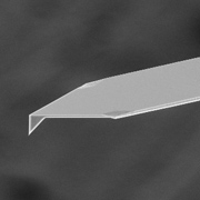
OMCL-AC240TS
New Silicon Cantilever for AC Mode

Aluminum reflex coating
OMCL-AC240TS-R3
(100 chips/box, Pre-separated chips)
OMCL-AC240TS-C3
(24 chips/box, Pre-separated chips)
No metal coating
OMCL-AC240TN-R3
(100 chips/box, Pre-separated chips)
OMCL-AC240TN-C3
(24 chips/box)
| Cantilever | |||||
|---|---|---|---|---|---|
| A | B | C | D | ||
| Lever types | - | - | - | ||
| Resonance Frequency fres |
[kHz] | 70 (50 - 90) |
|||
| Spring Constant kz |
[N/m] | 2
(0.6 - 3.5) |
|||
| Shape | Rectangular | ||||
| Length × Width × Thickness L × W × T |
[µm] | 240×40×2.3 | |||
| Probe setbac*1 D |
[µm] | 0 | |||
| Probe | |||||
|
|
|||||
| Shape | Tetrahedral | ||||
| Length | [µm] | 14 | |||
| Effective probe length*2 | [µm] | - | |||
| Tip radius R tip |
[nm] | 7 | |||
| Material | |||||
| Probe apex | Silicon (N type doped) | ||||
| Lever | Silicon (N type doped) | ||||
| Coating Metal | |||||
| Probe side | Non | ||||
| Reflex side | Aluminum | ||||
| chip | |||||
| type | New Concept Silicon Chip | ||||
| Length × Width × Thickness Lchip × Wchip × Tchip |
[mm] | 3.4×1.6×0.3 | |||
| Measurement mode | |||||
| Contact mode | - | ||||
| AC mode | |||||
| Measurement environments | |||||
| In air | |||||
| In water | - | ||||
- *1 Positive value of 'Probe setback' means the probe apex extends even further than the apex of the cantilever. Negative value means that the probe apex locates over the cantilever.
- *2 Effective probe length (Effective tip height) is defined as a length of distal part from the cantilever of two stage structured probe to clarify the length of the actual probe which smoothly grow in diameter from the probe apex toward the bottom.
- *3 Specifications are subject to change without any obligation on the part of the manufacturer.
| Cantilever | |||||
|---|---|---|---|---|---|
| A | B | C | D | ||
| Lever types | - | - | - | ||
| Resonance Frequency fres |
[kHz] | 70 (50 - 90) |
|||
| Spring Constant kz |
[N/m] | 2
(0.6 - 3.5) |
|||
| Shape | Rectangular | ||||
| Length × Width × Thickness L × W × T |
[µm] | 240×40×2.3 | |||
| Probe setbac*1 D |
[µm] | 0 | |||
| Probe | |||||
|
|
|||||
| Shape | Tetrahedral | ||||
| Length | [µm] | 14 | |||
| Effective probe length*2 | [µm] | - | |||
| Tip radius R tip |
[nm] | 7 | |||
| Material | |||||
| Probe apex | Silicon (N type doped) | ||||
| Lever | Silicon (N type doped) | ||||
| Coating Metal | |||||
| Probe side | Non | ||||
| Reflex side | Non | ||||
| chip | |||||
| type | New Concept Silicon Chip | ||||
| Length × Width × Thickness Lchip × Wchip × Tchip |
[mm] | 3.4×1.6×0.3 | |||
| Measurement mode | |||||
| Contact mode | - | ||||
| AC mode | |||||
| Measurement environments | |||||
| In air | |||||
| In water | |||||
- *1 Positive value of 'Probe setback' means the probe apex extends even further than the apex of the cantilever. Negative value means that the probe apex locates over the cantilever.
- *2 Effective probe length (Effective tip height) is defined as a length of distal part from the cantilever of two stage structured probe to clarify the length of the actual probe which smoothly grow in diameter from the probe apex toward the bottom.
- *3 Specifications are subject to change without any obligation on the part of the manufacturer.


